A Microprocessor is a programmable device that takes in input perform some arithmetic and logical operations over it and produce the desired output. In simple words, a Microprocessor is a digital device on a chip which can fetch instruction from memory, decode and execute them and give results.
Basics of Microprocessor: A Microprocessor takes a bunch of instructions in machine language and executes them, telling the processor what it has to do. Microprocessor performs three basic things while executing the instruction:
A typical Microprocessor structure looks like this.

Basics of Microprocessor: A Microprocessor takes a bunch of instructions in machine language and executes them, telling the processor what it has to do. Microprocessor performs three basic things while executing the instruction:
- It performs some basic operations like addition, subtraction, multiplication, division and some logical operations using its Arithmetic and Logical Unit (ALU). New Microprocessors also perform operations on floating-point numbers also.
- Data in the Microprocessor can move from one location to another.
- It has a Program Counter (PC) register that stores the address of next instruction based on the value of PC, Microprocessor jumps from one location to another and takes the decision.
A typical Microprocessor structure looks like this.
When a C program is compiled, the compiler generates object code. After generating the object code, the compiler also invokes the linker. One of the main tasks for linker is to make code of library functions (eg printf(), scanf(), sqrt(), ..etc) available to your program. A linker can accomplish this task in two ways, by copying the code of library function to your object code, known as Static Linking. Or by making some arrangements so that the complete code of library functions is not copied, but made available at run-time, known as Dynamic Linking.
- Static Linking and Static Libraries is the result of the linker making copy of all used library functions to the executable file. Static Linking creates larger binary files, and need more space on disk and main memory.
Examples of static libraries (libraries which are statically linked) are, .a files in Linux and .lib files in Windows.
- Dynamic linking and Dynamic Libraries Dynamic Linking doesn't require the code to be copied, it is done by just placing the name of the library in the binary file. The actual linking happens when the program is run when both the binary file and the library are in memory.
Examples of Dynamic libraries (libraries which are linked at run-time) are, .so in Linux and .dll in Windows.
A virtual function a member function which is declared within a base class and is re-defined(Overriden) by a derived class. When you refer to a derived class object using a pointer or a reference to the base class, you can call a virtual function for that object and execute the derived class's version of the function.
Example:
Complete Code/Output:
- Virtual functions ensure that the correct function is called for an object, regardless of the type of reference (or pointer) used for function call.
- They are mainly used to achieve Runtime polymorphism
- Functions are declared with a virtual keyword in base class.
- The resolving of function call is done at Run-time.
Example:
// CPP program to illustrate
// concept of Virtual Functions
#include <iostream>
using namespace std;
class base {
public:
virtual void print()
{
cout << "print base class" << endl;
}
void show()
{
cout << "show base class" << endl;
}
};
class derived : public base {
public:
void print()
{
cout << "print derived class" << endl;
}
void show()
{
cout << "show derived class" << endl;
}
// CPP program to illustrate
// concept of Virtual Functions

#include <iostream>
using namespace std;

class base {
public:
    virtual void print()
    {
        cout << "print base class" << endl;
    }

    void show()
    {
        cout << "show base class" << endl;
    }
};

class derived : public base {
public:
    void print()
    {
        cout << "print derived class" << endl;
    }

    void show()
    {
        cout << "show derived class" << endl;
    }
};

int main()
{
    base* bptr;
    derived d;
    bptr = &d;

    // virtual function, binded at runtime
    bptr->print();

    // Non-virtual function, binded at compile time
    bptr->show();
}
print derived class
show base class
In Dynamic binding compiler doesn't decide the method to be called. Overriding is a perfect example of dynamic binding. In overriding both parent and child classes have the same method.
Let's see an example:
Output:
Let's break down the code and understand it thoroughly.
Let's see an example:
public class NewClass
{
public static class superclass
{
void print()
{
System.out.println("print in superclass.");
}
}
public static class subclass extends superclass
{
@Override
void print()
{
System.out.println("print in subclass.");
}
}
public static void main(String[] args)
{
superclass A = new superclass();
superclass B = new subclass();
A.print();
B.print();
}
}
print in superclass.

print in subclass.
Let's break down the code and understand it thoroughly.
- Methods are not static in this code.
- During compilation, the compiler has no idea as to which print has to be called since compiler goes only by referencing variable not by the type of object and therefore the binding would be delayed to runtime and therefore the corresponding version of the print will be called based on type on object.
The idea is that virtual functions are called according to the type of the object instance pointed to or referenced, not according to the type of the pointer or reference.
In other words, virtual functions are resolved late, at runtime. So the compiler maintains two things to perform runtime resolution:

In other words, virtual functions are resolved late, at runtime. So the compiler maintains two things to perform runtime resolution:
- vtable: vtable is short form for Virtual Function Table. The virtual table is a lookup table of functions used to resolve function calls in a dynamic/late binding manner. The compiler creates a static table per class and the data consists of pointers to the virtual function definitions. They are automatically initialized by the compiler's constructor code. Since virtual function pointers are stored in each instance, the compiler is enabled to call the correct virtual function at runtime. First, every class that uses virtual functions (or is derived from a class that uses virtual functions) is given its own virtual table. Second, the compiler also adds a hidden pointer to the base class, which we will call *__vptr. *__vptr is set (automatically) when a class instance is created so that it points to the virtual table for that class.
- vptr: A pointer to vtable, maintained per object instance (see this for an example).

The concept of multi-threading needs proper understanding of these two terms - a process and a thread.

- A process is a program being executed. A process can be further divided into independent units known as threads.
- A thread is like a small light-weight process within a process. Or we can say a collection of threads is what is known as a process.
Difference between Process and Thread:
| S.NO | Process | Thread |
|---|---|---|
| 1. | Process means any program is in execution. | Thread means segment of a process. |
| 2. | Process takes more time to terminate. | Thread takes less time to terminate. |
| 3. | It takes more time for creation. | It takes less time for creation. |
| 4. | It also takes more time for context switching. | It takes less time for context switching. |
| 5. | Process is less efficient in term of communication. | Thread is more efficient in term of communication. |
| 6. | Process consume more resources. | Thread consume less resources. |
| 7. | Process is isolated. | Threads share memory. |
First in, first out (FIFO), also known as first come, first served (FCFS), is the simplest scheduling algorithm. FIFO simply queues processes in the order that they arrive in the ready queue.
In this, the process that comes first will be executed first and the next process starts only after the previous gets fully executed.
Here we are considering that arrival time for all processes is 0.

Implementation:
In this, the process that comes first will be executed first and the next process starts only after the previous gets fully executed.
Here we are considering that arrival time for all processes is 0.
Implementation:
1-  Input the processes along with their burst time (bt).
2-  Find waiting time (wt) for all processes.
3-  As first process that comes need not to wait so
    waiting time for process 1 will be 0 i.e. wt[0] = 0.
4-  Find waiting time for all other processes i.e. for
     process i ->
       wt[i] = bt[i-1] + wt[i-1] .
5-  Find turnaround time = waiting_time + burst_time
    for all processes.
6-  Find average waiting time =
                 total_waiting_time / no_of_processes.
7-  Similarly, find average turnaround time =
                 total_turn_around_time / no_of_processes.
Shortest job first (SJF) or shortest job next, is a scheduling policy that selects the waiting process with the smallest execution time to execute next. SJN is a non-preemptive algorithm.
How to compute below times in SJF using a program?
Algorithm:

- Shortest Job first has the advantage of having a minimum average waiting time among all scheduling algorithms.
- It is a Greedy Algorithm.
- It may cause starvation if shorter processes keep coming. This problem can be solved using the concept of ageing.
- It is practically infeasible as Operating System may not know burst time and therefore may not sort them. While it is not possible to predict execution time, several methods can be used to estimate the execution time for a job, such as a weighted average of previous execution times. SJF can be used in specialized environments where accurate estimates of running time are available.
How to compute below times in SJF using a program?
- Completion Time: Time at which process completes its execution.
- Turn Around Time: Time Difference between completion time and arrival time. Turn Around Time = Completion Time - Arrival Time
- Waiting Time(W.T): Time Difference between turn around time and burst time.
Waiting Time = Turn Around Time - Burst Time
Algorithm:
- Sort all the process according to the arrival time.
- Then select that process which has minimum arrival time and minimum Burst time.
- After completion of process make a pool of process which after till the completion of previous process and select that process among the pool which is having minimum Burst time.
In the Shortest Remaining Time First (SRTF) scheduling algorithm, the process with the smallest amount of time remaining until completion is selected to execute. Since the currently executing process is the one with the shortest amount of time remaining by definition, and since that time should only reduce as execution progresses, processes will always run until they complete or a new process is added that requires a smaller amount of time.
Implementation:
Shortest Remaining Time First (Preemptive SJF): Example
P1 waiting time: 4-2 = 2
P2 waiting time: 0
The average waiting time(AWT): (0 + 2) / 2 = 1
Implementation:
1- Traverse until all process gets completely
   executed.
   a) Find process with minimum remaining time at
     every single time lap.
   b) Reduce its time by 1.
   c) Check if its remaining time becomes 0
   d) Increment the counter of process completion.
   e) Completion time of current process =
     current_time +1;
   e) Calculate waiting time for each completed
     process.
   wt[i]= Completion time - arrival_time-burst_time
   f)Increment time lap by one.
2- Find turnaround time (waiting_time+burst_time).
This is a pre-emptive version of Longest Job First (LJF) scheduling algorithm. In this scheduling algorithm, we find the process with the maximum remaining time and then process it. We check for the maximum remaining time after some interval of time(say 1 unit each) to check if another process having more Burst Time arrived up to that time.
Procedure:
Example-1: Consider the following table of arrival time and burst time for four processes P1, P2, P3 and P4.
Working: (for input 1):
Note that CPU will be idle for 0 to 1 unit time since there is no process available in the given interval.
Gantt chart will be as following below,

Since, complietion time (CT) can be directly determined by Gantt chart, and
Therefore, final table look like,

Output:
Procedure:
- Step-1: First, sort the processes in increasing order of their Arrival Time.
- Step-2: Choose the process having least arrival time but with most Burst Time. Then process it for 1 unit. Check if any other process arrives upto that time of execution or not.
- Step-3: Repeat the above both steps until execute all the processes.
Example-1: Consider the following table of arrival time and burst time for four processes P1, P2, P3 and P4.
Process   Arrival time   Burst Time

P1            1 ms          2 ms

P2            2 ms          4 ms

P3            3 ms          6 ms

P4            4 ms          8 ms
Working: (for input 1):
- At t = 1, Available Process : P1. So, select P1 and execute 1 ms.
- At t = 2, Available Process : P1, P2. So, select P2 and execute 1 ms (since BT(P1)=1 which is less than BT(P2) = 4)
- At t = 3, Available Process : P1, P2, P3. So, select P3 and execute 1 ms (since, BT(P1) = 1 , BT(P2) = 3 , BT(P3) = 6).
- Repeat the above steps until the execution of all processes.
Note that CPU will be idle for 0 to 1 unit time since there is no process available in the given interval.
Gantt chart will be as following below,
Since, complietion time (CT) can be directly determined by Gantt chart, and
Turn Around Time (TAT)

= (Complition Time) - (Arival Time)


Also, Waiting Time (WT)

= (Turn Around Time) - (Burst Time)
Therefore, final table look like,
Output:
Total Turn Around Time = 68 ms

So, Average Turn Around Time = 68/4 = 17.00 ms


And, Total Waiting Time = 48 ms

So Average Waiting Time = 48/4 = 12.00 ms
Priority scheduling is one of the most common scheduling algorithms in batch systems. Each process is assigned a priority. The process with the highest priority is to be executed first and so on.
Processes with the same priority are executed on a first-come-first-served basis. Priority can be decided based on memory requirements, time requirements or any other resource requirement.
Implementation:

Note: A major problem with priority scheduling is indefinite blocking or starvation. A solution to the problem of indefinite blockage of the low-priority process is ageing. Ageing is a technique of gradually increasing the priority of processes that wait in the system for a long period of time.
Processes with the same priority are executed on a first-come-first-served basis. Priority can be decided based on memory requirements, time requirements or any other resource requirement.
Implementation:
1- First input the processes with their burst time
   and priority.
2- Sort the processes, burst time and priority
   according to the priority.
3- Now simply apply FCFS algorithm.

Note: A major problem with priority scheduling is indefinite blocking or starvation. A solution to the problem of indefinite blockage of the low-priority process is ageing. Ageing is a technique of gradually increasing the priority of processes that wait in the system for a long period of time.
Round Robin is a CPU scheduling algorithm where each process is assigned a fixed time slot in a cyclic way.
Illustration:
How to compute below times in Round Robin using a program?
- It is simple, easy to implement, and starvation-free as all processes get fair share of CPU.
- One of the most commonly used technique in CPU scheduling as a core.
- It is preemptive as processes are assigned CPU only for a fixed slice of time at most.
- The disadvantage of it is more overhead of context switching.
Illustration:
How to compute below times in Round Robin using a program?
- Completion Time: Time at which process completes its execution.
- Turn Around Time: Time Difference between completion time and arrival time. Turn Around Time = Completion Time - Arrival Time
- Waiting Time(W.T): Time Difference between turn around time and burst time.
Waiting Time = Turn Around Time - Burst Time
Semaphore was proposed by Dijkstra in 1965 which is a very significant technique to manage concurrent processes by using a simple integer value, which is known as a semaphore. Semaphore is simply a variable which is non-negative and shared between threads. This variable is used to solve the critical section problem and to achieve process synchronization in the multiprocessing environment.
Semaphores are of two types:
Semaphores are of two types:
- Binary Semaphore: This is also known as mutex lock. It can have only two values - 0 and 1. Its value is initialized to 1. It is used to implement the solution of critical section problem with multiple processes.
- Counting Semaphore: Its value can range over an unrestricted domain. It is used to control access to a resource that has multiple instances.
- A Mutex is a lock that we set before using a shared resource and release after using it.
- When the lock is set, no other thread can access the locked region of code.
- So we see that even if thread 2 is scheduled while thread 1 was not done accessing the shared resource and the code is locked by thread 1 using mutexes then thread 2 cannot even access that region of code.
- So this ensures synchronized access of shared resources in the code.
Working of a mutex
- Suppose one thread has locked a region of code using mutex and is executing that piece of code.
- Now if scheduler decides to do a context switch, then all the other threads which are ready to execute the same region are unblocked.
- Only one of all the threads would make it to the execution but if this thread tries to execute the same region of code that is already locked then it will again go to sleep.
- Context switch will take place again and again but no thread would be able to execute the locked region of code until the mutex lock over it is released.
- Mutex lock will only be released by the thread who locked it.
- So this ensures that once a thread has locked a piece of code then no other thread can execute the same region until it is unlocked by the thread who locked it.
Hence, this system ensures synchronization among the threads while working on shared resources.
Consider the standard producer-consumer problem. Assume, we have a buffer of 4096-byte length. A producer thread collects the data and writes it to the buffer. A consumer thread processes the collected data from the buffer. The objective is, both the threads should not run at the same time.
Using Mutex:
A mutex provides mutual exclusion, either producer or consumer can have the key (mutex) and proceed with their work. As long as the buffer is filled by the producer, the consumer needs to wait, and vice versa.
At any point of time, only one thread can work with the entire buffer. The concept can be generalized using a semaphore.
Using Semaphore:
A semaphore is a generalized mutex. In lieu of single buffer, we can split the 4 KB buffer into four 1 KB buffers (identical resources). A semaphore can be associated with these four buffers. The consumer and producer can work on different buffers at the same time.
In computing, the producer-consumer problem (also known as the bounded-buffer problem) is a classic example of a multi-process synchronization problem. The problem describes two processes, the producer and the consumer, which share a common, fixed-size buffer used as a queue.
Problem
To make sure that the producer won't try to add data into the buffer if it's full and that the consumer won't try to remove data from an empty buffer.
Solution: The producer is to either go to sleep or discard data if the buffer is full. The next time the consumer removes an item from the buffer, it notifies the producer, who starts to fill the buffer again. In the same way, the consumer can go to sleep if it finds the buffer to be empty. The next time the producer puts data into the buffer, it wakes up the sleeping consumer.
An inadequate solution could result in a deadlock where both processes are waiting to be awakened.
In the post Producer-Consumer solution using threads in Java, we have discussed above solution by using inter-thread communication(wait(), notify(), sleep()). In this post, we will use Semaphores to implement the same.
The below solution consists of four classes:
Complete Code/Output:
Explanation : As you can see, the calls to put() and get( ) are synchronized, i.e. each call to put() is followed by a call to get( ) and no items are missed. Without the semaphores, multiple calls to put() would have occurred without matching calls to get(), resulting in items being missed. (To prove this, remove the semaphore code and observe the results.)
The sequencing of put() and get() calls is handled by two semaphores: semProd and semCon.
- The producer's job is to generate data, put it into the buffer, and start again.
- At the same time, the consumer is consuming the data (i.e. removing it from the buffer), one piece at a time.
Problem
To make sure that the producer won't try to add data into the buffer if it's full and that the consumer won't try to remove data from an empty buffer.
Solution: The producer is to either go to sleep or discard data if the buffer is full. The next time the consumer removes an item from the buffer, it notifies the producer, who starts to fill the buffer again. In the same way, the consumer can go to sleep if it finds the buffer to be empty. The next time the producer puts data into the buffer, it wakes up the sleeping consumer.
An inadequate solution could result in a deadlock where both processes are waiting to be awakened.
In the post Producer-Consumer solution using threads in Java, we have discussed above solution by using inter-thread communication(wait(), notify(), sleep()). In this post, we will use Semaphores to implement the same.
The below solution consists of four classes:
- Q : the queue that you’re trying to synchronize
- Producer : the threaded object that is producing queue entries
- Consumer : the threaded object that is consuming queue entries
- PC : the driver class that creates the single Q, Producer, and Consumer.
// Java implementation of a producer and consumer
// that use semaphores to control synchronization.
import java.util.concurrent.Semaphore;
class Q
{
// an item
int item;
// semCon initialized with 0 permits
// to ensure put() executes first
static Semaphore semCon = new Semaphore(0);
static Semaphore semProd = new Semaphore(1);
// to get an item from buffer
void get()
{
try {
// Before consumer can consume an item,
// it must acquire a permit from semCon
semCon.acquire();
}
catch(InterruptedException e) {
System.out.println("InterruptedException caught");
}
// consumer consuming an item
System.out.println("Consumer consumed item : " + item);
// Java implementation of a producer and consumer
// that use semaphores to control synchronization.

import java.util.concurrent.Semaphore;

class Q
{
    // an item
    int item;

    // semCon initialized with 0 permits
    // to ensure put() executes first
    static Semaphore semCon = new Semaphore(0);

    static Semaphore semProd = new Semaphore(1);

    // to get an item from buffer
    void get()
    {
        try {
            // Before consumer can consume an item,
            // it must acquire a permit from semCon
            semCon.acquire();
        }
        catch(InterruptedException e) {
            System.out.println("InterruptedException caught");
        }

        // consumer consuming an item
        System.out.println("Consumer consumed item : " + item);

        // After consumer consumes the item,
        // it releases semProd to notify producer
        semProd.release();
    }

    // To put an item in buffer
    void put(int item)
    {
        try {
            // Before producer can produce an item,
            // it must acquire a permit from semProd
            semProd.acquire();
        } catch(InterruptedException e) {
            System.out.println("InterruptedException caught");
        }

        // producer producing an item
        this.item = item;

        System.out.println("Producer produced item : " + item);

        // After producer produces the item,
        // it releases semCon to notify consumer
        semCon.release();
    }
}

// Producer class
class Producer implements Runnable
{
    Q q;
    Producer(Q q) {
        this.q = q;
        new Thread(this, "Producer").start();
    }

    public void run() {
        for(int i=0; i < 5; i++)
            // producer put items
            q.put(i);
    }
}

// Consumer class
class Consumer implements Runnable
{
    Q q;
    Consumer(Q q){
        this.q = q;
        new Thread(this, "Consumer").start();
    }

    public void run()
    {
        for(int i=0; i < 5; i++)
            // consumer get items
            q.get();
    }
}

// Driver class
class PC
{
    public static void main(String args[])
    {
        // creating buffer queue
        Q q = new Q();

        // starting consumer thread
        new Consumer(q);

        // starting producer thread
        new Producer(q);
    }
}
Producer produced item : 0
Consumer consumed item : 0
Producer produced item : 1
Consumer consumed item : 1
Producer produced item : 2
Consumer consumed item : 2
Producer produced item : 3
Consumer consumed item : 3
Producer produced item : 4
Consumer consumed item : 4
Explanation : As you can see, the calls to put() and get( ) are synchronized, i.e. each call to put() is followed by a call to get( ) and no items are missed. Without the semaphores, multiple calls to put() would have occurred without matching calls to get(), resulting in items being missed. (To prove this, remove the semaphore code and observe the results.)
The sequencing of put() and get() calls is handled by two semaphores: semProd and semCon.
- Before put( ) can produce an item, it must acquire a permit from semProd. After it has produce the item, it releases semCon.
- Before get( ) can consume an item, it must acquire a permit from semCon. After it consumes the item, it releases semProd.
- This "give and take" mechanism ensures that each call to put( ) must be followed by a call to get( ).
- Also notice that semCon is initialized with no available permits. This ensures that put( ) executes first. The ability to set the initial synchronization state is one of the more powerful aspects of a semaphore.
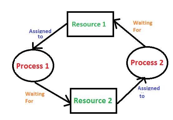
Deadlock is a situation where a set of processes are blocked because each process is holding a resource and waiting for another resource acquired by some other process.
Consider an example when two trains are coming toward each other on the same track and there is only one track, none of the trains can move once they are in front of each other. A similar situation occurs in operating systems when there are two or more processes hold some resources and wait for resources held by other(s). For example, in the below diagram, Process 1 is holding Resource 1 and waiting for resource 2 which is acquired by process 2, and process 2 is waiting for resource 1.

Necessary Conditions for Deadlock to occur Deadlock can arise if the following four conditions hold simultaneously
Consider an example when two trains are coming toward each other on the same track and there is only one track, none of the trains can move once they are in front of each other. A similar situation occurs in operating systems when there are two or more processes hold some resources and wait for resources held by other(s). For example, in the below diagram, Process 1 is holding Resource 1 and waiting for resource 2 which is acquired by process 2, and process 2 is waiting for resource 1.
Necessary Conditions for Deadlock to occur Deadlock can arise if the following four conditions hold simultaneously
- Mutual Exclusion: One or more than one resource are non-sharable (Only one process can use at a time)
- Hold and Wait: A process is holding at least one resource and waiting for resources.
- No Preemption: A resource cannot be taken from a process unless the process releases the resource.
- Circular Wait: A set of processes are waiting for each other in circular form.
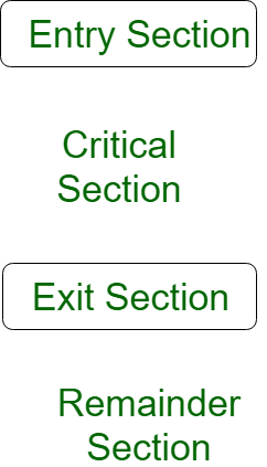
When more than one processes access the same code segment that segment is known as critical section. The critical section contains shared variables or resources which are needs to be synchronized to maintain consistency of data variable.
In simple terms a critical section is group of instructions/statements or region of code that need to be executed atomically (read this post for atomicity), such as accessing a resource (file, input or output port, global data, etc.).
In concurrent programming, if one thread tries to change the value of shared data at the same time as another thread tries to read the value (i.e. data race across threads), the result is unpredictable.
The access to such shared variable (shared memory, shared files, shared port, etc...) to be synchronized. Few programming languages have built-in support for synchronization.
It is critical to understand the importance of race condition while writing kernel-mode programming (a device driver, kernel thread, etc.). since the programmer can directly access and modifying kernel data structures.
The banker’s algorithm is a resource allocation and deadlock avoidance algorithm that tests for safety by simulating the allocation for predetermined maximum possible amounts of all resources, then makes an “s-state” check to test for possible activities, before deciding whether allocation should be allowed to continue.
Following Data structures are used to implement the Banker’s Algorithm:
Let ‘n’ be the number of processes in the system and ‘m’ be the number of resources types.
Available :
Allocationi specifies the resources currently allocated to process Pi and Needi specifies the additional resources that process Pi may still request to complete its task.
Banker's algorithm consists of Safety algorithm and Resource request algorithm
Safety Algorithm
The algorithm for finding out whether or not a system is in a safe state can be described as follows:
Resource-Request Algorithm
Let Requesti be the request array for process Pi. Requesti [j] = k means process Pi wants k instances of resource type Rj. When a request for resources is made by process Pi, the following actions are taken:
Following Data structures are used to implement the Banker’s Algorithm:
Let ‘n’ be the number of processes in the system and ‘m’ be the number of resources types.
Available :
- It is a 1-d array of size ‘m’ indicating the number of available resources of each type.
- Available[ j ] = k means there are ‘k’ instances of resource type Rj
- It is a 2-d array of size ‘n*m’ that defines the maximum demand of each process in a system.
- Max[ i, j ] = k means process Pi may request at most ‘k’ instances of resource type Rj.
- It is a 2-d array of size ‘n*m’ that defines the number of resources of each type currently allocated to each process.
- Allocation[ i, j ] = k means process Pi is currently allocated ‘k’ instances of resource type Rj
- It is a 2-d array of size ‘n*m’ that indicates the remaining resource need of each process.
- Need [ i, j ] = k means process Pi currently need ‘k’ instances of resource type Rj for its execution.
- Need [ i, j ] = Max [ i, j ] – Allocation [ i, j ]
Allocationi specifies the resources currently allocated to process Pi and Needi specifies the additional resources that process Pi may still request to complete its task.
Banker's algorithm consists of Safety algorithm and Resource request algorithm
Safety Algorithm
The algorithm for finding out whether or not a system is in a safe state can be described as follows:
1) Let Work and Finish be vectors of length 'm' and 'n' respectively.
Initialize: Work = Available
Finish[i] = false; for i=1, 2, 3, 4....n
2) Find an i such that both
a) Finish[i] = false
b) Needi <= Work
if no such i exists goto step (4)
3) Work = Work + Allocation[i]
Finish[i] = true
goto step (2)
4) if Finish [i] = true for all i
then the system is in a safe state
Resource-Request Algorithm
Let Requesti be the request array for process Pi. Requesti [j] = k means process Pi wants k instances of resource type Rj. When a request for resources is made by process Pi, the following actions are taken:
1) If Requesti <= Needi Goto step (2) ; otherwise, raise an error condition, since the process has exceeded its maximum claim.
2) If Requesti <= Available
Goto step (3); otherwise, Pi must wait, since the resources are not available.
3) Have the system pretend to have allocated the requested resources to process Pi by modifying the state as
follows:
Available = Available - Requesti
Allocationi = Allocationi + Requesti Needi = Needi- Requesti
A spinlock is a lock which causes a thread trying to acquire it to simply wait in a loop ("spin") while repeatedly checking if the lock is available. Since the thread remains active but is not performing a useful task, the use of such a lock is a kind of busy waiting.
Spinlocks are not appropriate for single-processor systems because the condition that would break a process out of the spinlock can be obtained only by executing a different process. If the process is not relinquishing the processor, other processes do not get the opportunity to set the program condition required for the first process to make progress. In a multiprocessor system, other processes execute on other processors and thereby modify the program state in order to release the first process from the spinlock.
Spinlocks are not appropriate for single-processor systems because the condition that would break a process out of the spinlock can be obtained only by executing a different process. If the process is not relinquishing the processor, other processes do not get the opportunity to set the program condition required for the first process to make progress. In a multiprocessor system, other processes execute on other processors and thereby modify the program state in order to release the first process from the spinlock.
Cache Memory is a special very high-speed memory. It is used to speed up and synchronizing with high-speed CPU. Cache memory is costlier than main memory or disk memory but economical than CPU registers. Cache memory is an extremely fast memory type that acts as a buffer between RAM and the CPU. It holds frequently requested data and instructions so that they are immediately available to the CPU when needed.
Cache memory is used to reduce the average time to access data from the Main memory. The cache is a smaller and faster memory which stores copies of the data from frequently used main memory locations. There are various different independent caches in a CPU, which store instructions and data.

Levels of memory:
Cache memory is used to reduce the average time to access data from the Main memory. The cache is a smaller and faster memory which stores copies of the data from frequently used main memory locations. There are various different independent caches in a CPU, which store instructions and data.
Levels of memory:
- Level 1 or Register -
It is a type of memory in which data is stored and accepted that are immediately stored in CPU. Most commonly used register is accumulator, Program counter, address register etc. - Level 2 or Cache memory -
It is the fastest memory which has faster access time where data is temporarily stored for faster access. - Level 3 or Main Memory -
It is memory on which computer works currently. It is small in size and once power is off data no longer stays in this memory. - Level 4 or Secondary Memory -
It is external memory which is not as fast as main memory but data stays permanently in this memory.
The process of loading the page into memory on demand (whenever page fault occurs) is known as demand paging.
The process includes the following steps :

Hence whenever a page fault occurs these steps are followed by the operating system and the required page is brought into memory.
The process includes the following steps :

- If CPU try to refer a page that is currently not available in the main memory, it generates an interrupt indicating memory access fault.
- The OS puts the interrupted process in a blocking state. For the execution to proceed the OS must bring the required page into the memory.
- The OS will search for the required page in the logical address space.
- The required page will be brought from logical address space to physical address space. The page replacement algorithms are used for the decision making of replacing the page in physical address space.
- The page table will updated accordingly.
- The signal will be sent to the CPU to continue the program execution and it will place the process back into ready state.
Hence whenever a page fault occurs these steps are followed by the operating system and the required page is brought into memory.
Thrashing is a condition or a situation when the system is spending a major portion of its time in servicing the page faults, but the actual processing done is very negligible.

The basic concept involved is that if a process is allocated too few frames, then there will be too many and too frequent page faults. As a result, no useful work would be done by the CPU and the CPU utilisation would fall drastically. The long-term scheduler would then try to improve the CPU utilisation by loading some more processes into the memory thereby increasing the degree of multiprogramming. This would result in a further decrease in the CPU utilization triggering a chained reaction of higher page faults followed by an increase in the degree of multiprogramming, called Thrashing.
The basic concept involved is that if a process is allocated too few frames, then there will be too many and too frequent page faults. As a result, no useful work would be done by the CPU and the CPU utilisation would fall drastically. The long-term scheduler would then try to improve the CPU utilisation by loading some more processes into the memory thereby increasing the degree of multiprogramming. This would result in a further decrease in the CPU utilization triggering a chained reaction of higher page faults followed by an increase in the degree of multiprogramming, called Thrashing.
A process is divided into Segments. The chunks that a program is divided into which are not necessarily all of the same sizes are called segments. Segmentation gives user's view of the process which paging does not give. Here the user's view is mapped to physical memory.
There are types of segmentation:
There is no simple relationship between logical addresses and physical addresses in segmentation. A table stores the information about all such segments and is called Segment Table.
Segment Table - It maps two-dimensional Logical address into one-dimensional Physical address. It's each table entry has:

Translation of Two-dimensional Logical Address to one-dimensional Physical Address.

Address generated by the CPU is divided into:
There are types of segmentation:
- Virtual memory segmentation -
Each process is divided into a number of segments, not all of which are resident at any one point in time.
- Simple segmentation -
Each process is divided into a number of segments, all of which are loaded into memory at run time, though not necessarily contiguously.
There is no simple relationship between logical addresses and physical addresses in segmentation. A table stores the information about all such segments and is called Segment Table.
Segment Table - It maps two-dimensional Logical address into one-dimensional Physical address. It's each table entry has:
- Base Address: It contains the starting physical address where the segments reside in memory.
- Limit: It specifies the length of the segment.
Translation of Two-dimensional Logical Address to one-dimensional Physical Address.
Address generated by the CPU is divided into:
- Segment number (s): Number of bits required to represent the segment.
- Segment offset (d): Number of bits required to represent the size of the segment.
In Java, all objects are stored in the heap. They are allocated using new operator. The OutOfMemoryError Exception in Java looks like this:
OutOfMemoryError usually means that you're doing something wrong, either holding onto objects too long or trying to process too much data at a time. Sometimes, it indicates a problem that's out of your control, such as a third-party library that caches strings, or an application server that doesn't clean up after deploys. And sometimes, it has nothing to do with objects on the heap.
The java.lang.OutOfMemoryError exception can also be thrown by native library code when a native allocation cannot be satisfied (for example, if swap space is low).
Exception in thread "main" java.lang.OutOfMemoryError: Java heap spaceUsually, this error is thrown when the Java Virtual Machine cannot allocate an object because it is out of memory, and no more memory could be made available by the garbage collector.
OutOfMemoryError usually means that you're doing something wrong, either holding onto objects too long or trying to process too much data at a time. Sometimes, it indicates a problem that's out of your control, such as a third-party library that caches strings, or an application server that doesn't clean up after deploys. And sometimes, it has nothing to do with objects on the heap.
The java.lang.OutOfMemoryError exception can also be thrown by native library code when a native allocation cannot be satisfied (for example, if swap space is low).
There are two types of fragmentation in OS which are given as Internal fragmentation, and External fragmentation.
Internal Fragmentation: Internal fragmentation happens when the memory is split into mounted sized blocks. Whenever a method request for the memory, the mounted sized block is allotted to the method. just in case the memory allotted to the method is somewhat larger than the memory requested, then the distinction between allotted and requested memory is that the internal fragmentation.

The above diagram clearly shows the internal fragmentation because the difference between memory allocated and required space or memory is called Internal fragmentation.
External Fragmentation:
External fragmentation happens when there's a sufficient quantity of area within the memory to satisfy the memory request of a method. however, the process’s memory request cannot be happy because the memory offered is during a non-contiguous manner. Either you apply first-fit or best-fit memory allocation strategy it'll cause external fragmentation.

In above diagram, we can see that, there is enough space (55 KB) to run a process-07 (required 50 KB) but the memory (fragment) is not contiguous. Here, we use compaction, paging or segmentation to use the free space to run a process.
Internal Fragmentation: Internal fragmentation happens when the memory is split into mounted sized blocks. Whenever a method request for the memory, the mounted sized block is allotted to the method. just in case the memory allotted to the method is somewhat larger than the memory requested, then the distinction between allotted and requested memory is that the internal fragmentation.
The above diagram clearly shows the internal fragmentation because the difference between memory allocated and required space or memory is called Internal fragmentation.
External Fragmentation:
External fragmentation happens when there's a sufficient quantity of area within the memory to satisfy the memory request of a method. however, the process’s memory request cannot be happy because the memory offered is during a non-contiguous manner. Either you apply first-fit or best-fit memory allocation strategy it'll cause external fragmentation.
In above diagram, we can see that, there is enough space (55 KB) to run a process-07 (required 50 KB) but the memory (fragment) is not contiguous. Here, we use compaction, paging or segmentation to use the free space to run a process.
Direct Mapping
The simplest technique, known as direct mapping, maps each block of main memory into only one possible cache line. or
In Direct mapping, assign each memory block to a specific line in the cache. If a line is previously taken up by a memory block when a new block needs to be loaded, the old block is trashed. An address space is split into two parts index field and a tag field. The cache is used to store the tag field whereas the rest is stored in the main memory. Direct mapping`s performance is directly proportional to the Hit ratio.
For purposes of cache access, each main memory address can be viewed as consisting of three fields. The least significant w bits identify a unique word or byte within a block of main memory. In most contemporary machines, the address is at the byte level. The remaining s bits specify one of the 2s blocks of main memory. The cache logic interprets these s bits as a tag of s-r bits (most significant portion) and a line field of r bits. This latter field identifies one of the m=2r lines of the cache.


Associative Mapping In this type of mapping, the associative memory is used to store content and addresses of the memory word. Any block can go into any line of the cache. This means that the word id bits are used to identify which word in the block is needed, but the tag becomes all of the remaining bits. This enables the placement of any word at any place in the cache memory. It is considered to be the fastest and the most flexible mapping form.

In Direct mapping, assign each memory block to a specific line in the cache. If a line is previously taken up by a memory block when a new block needs to be loaded, the old block is trashed. An address space is split into two parts index field and a tag field. The cache is used to store the tag field whereas the rest is stored in the main memory. Direct mapping`s performance is directly proportional to the Hit ratio.
i = j modulo m

where

i=cache line number

j= main memory block number

m=number of lines in the cache
For purposes of cache access, each main memory address can be viewed as consisting of three fields. The least significant w bits identify a unique word or byte within a block of main memory. In most contemporary machines, the address is at the byte level. The remaining s bits specify one of the 2s blocks of main memory. The cache logic interprets these s bits as a tag of s-r bits (most significant portion) and a line field of r bits. This latter field identifies one of the m=2r lines of the cache.
Associative Mapping In this type of mapping, the associative memory is used to store content and addresses of the memory word. Any block can go into any line of the cache. This means that the word id bits are used to identify which word in the block is needed, but the tag becomes all of the remaining bits. This enables the placement of any word at any place in the cache memory. It is considered to be the fastest and the most flexible mapping form.
Paging is a memory management scheme that eliminates the need for contiguous allocation of physical memory. This scheme permits the physical address space of a process to be non - contiguous.
Example:
The mapping from virtual to physical address is done by the memory management unit (MMU) which is a hardware device and this mapping is known as paging technique.
- Logical Address or Virtual Address (represented in bits): An address generated by the CPU
- Logical Address Space or Virtual Address Space( represented in words or bytes): The set of all logical addresses generated by a program
- Physical Address (represented in bits): An address actually available on memory unit
- Physical Address Space (represented in words or bytes): The set of all physical addresses corresponding to the logical addresses
Example:
- If Logical Address = 31 bit, then Logical Address Space = 231 words = 2 G words (1 G = 230)
- If Logical Address Space = 128 M words = 27 * 220 words, then Logical Address = log2 227 = 27 bits
- If Physical Address = 22 bit, then Physical Address Space = 222 words = 4 M words (1 M = 220)
- If Physical Address Space = 16 M words = 24 * 220 words, then Physical Address = log2 224 = 24 bits
The mapping from virtual to physical address is done by the memory management unit (MMU) which is a hardware device and this mapping is known as paging technique.
- The Physical Address Space is conceptually divided into a number of fixed-size blocks, called frames.
- The Logical address Space is also splitted into fixed-size blocks, called pages.
- Page Size = Frame Size
Page table has page table entries where each page table entry stores a frame number and optional status (like protection) bits. Many of the status bits used in the virtual memory system. The most important thing in PTE is frame Number.
Page table entry has the following information -

Page table entry has the following information -
- Frame Number - It gives the frame number in which the current page you are looking for is present. The number of bits required depends on the number of frames.Frame bit is also known as address translation bit.
Number of bits for frame = Size of physical memory/frame size
- Present/Absent bit - Present or absent bit says whether a particular page you are looking for is present or absent. In case if it is not present, that is called Page Fault. It is set to 0 if the corresponding page is not in memory. Used to control page fault by the operating system to support virtual memory. Sometimes this bit is also known as valid/invalid bits.
- Protection bit - Protection bit says that what kind of protection you want on that page. So, these bits for the protection of the page frame (read, write etc).
- Referenced bit - Referenced bit will say whether this page has been referred in the last clock cycle or not. It is set to 1 by hardware when the page is accessed.
- Caching enabled/disabled - Some times we need the fresh data. Let us say the user is typing some information from the keyboard and your program should run according to the input given by the user. In that case, the information will come into the main memory. Therefore the main memory contains the latest information which is typed by the user. Now if you try to put that page in the cache, that cache will show the old information. So whenever freshness is required, we don't want to go for caching or many levels of the memory. The information present in the closest level to the CPU and the information present at the closest level to the user might be different. So we want the information has to be consistency, which means whatever information user has given, CPU should be able to see it as first as possible. That is the reason we want to disable caching. So, this bit enables or disable caching of the page.
- Modified bit - Modified bit says whether the page has been modified or not. Modified means sometimes you might try to write something on to the page. If a page is modified, then whenever you should replace that page with some other page, then the modified information should be kept on the hard disk or it has to be written back or it has to be saved back. It is set to 1 by hardware on write-access to page which is used to avoid writing when swapped out. Sometimes this modified bit is also called as the Dirty bit.
In Operating System (Memory Management Technique : Paging), for each process page table will be created, which will contain Page Table Entry (PTE). This PTE will contain information like frame number (The address of main memory where we want to refer), and some other useful bits (e.g., valid/invalid bit, dirty bit, protection bit etc). This page table entry (PTE) will tell where in the main memory the actual page is residing.
Now the question is where to place the page table, such that overall access time (or reference time) will be less.
The problem initially was to fast access the main memory content based on address generated by CPU (i.e logical/virtual address). Initially, some people thought of using registers to store page table, as they are high-speed memory so access time will be less.
The idea used here is, place the page table entries in registers, for each request generated from CPU (virtual address), it will be matched to the appropriate page number of the page table, which will now tell where in the main memory that corresponding page resides. Everything seems right here, but the problem is register size is small (in practical, it can accommodate maximum of 0.5k to 1k page table entries) and process size may be big hence the required page table will also be big (lets say this page table contains 1M entries), so registers may not hold all the PTE's of Page table. So this is not a practical approach.
To overcome this size issue, the entire page table was kept in main memory. but the problem here is two main memory references are required:
To overcome this problem a high-speed cache is set up for page table entries called a Translation Lookaside Buffer (TLB). Translation Lookaside Buffer (TLB) is nothing but a special cache used to keep track of recently used transactions. TLB contains page table entries that have been most recently used. Given a virtual address, the processor examines the TLB if a page table entry is present (TLB hit), the frame number is retrieved and the real address is formed. If a page table entry is not found in the TLB (TLB miss), the page number is used to index the process page table. TLB first checks if the page is already in main memory, if not in main memory a page fault is issued then the TLB is updated to include the new page entry.

Steps in TLB hit:
Steps in Page miss:
EMAT = h*(c+m) + (1-h)*(c+2m)
where, h = hit ratio of TLB
m = Memory access time
c = TLB access time
Now the question is where to place the page table, such that overall access time (or reference time) will be less.
The problem initially was to fast access the main memory content based on address generated by CPU (i.e logical/virtual address). Initially, some people thought of using registers to store page table, as they are high-speed memory so access time will be less.
The idea used here is, place the page table entries in registers, for each request generated from CPU (virtual address), it will be matched to the appropriate page number of the page table, which will now tell where in the main memory that corresponding page resides. Everything seems right here, but the problem is register size is small (in practical, it can accommodate maximum of 0.5k to 1k page table entries) and process size may be big hence the required page table will also be big (lets say this page table contains 1M entries), so registers may not hold all the PTE's of Page table. So this is not a practical approach.
To overcome this size issue, the entire page table was kept in main memory. but the problem here is two main memory references are required:
- To find the frame number
- To go to the address specified by frame number
To overcome this problem a high-speed cache is set up for page table entries called a Translation Lookaside Buffer (TLB). Translation Lookaside Buffer (TLB) is nothing but a special cache used to keep track of recently used transactions. TLB contains page table entries that have been most recently used. Given a virtual address, the processor examines the TLB if a page table entry is present (TLB hit), the frame number is retrieved and the real address is formed. If a page table entry is not found in the TLB (TLB miss), the page number is used to index the process page table. TLB first checks if the page is already in main memory, if not in main memory a page fault is issued then the TLB is updated to include the new page entry.
Steps in TLB hit:
- CPU generates virtual address.
- It is checked in TLB (present).
- Corresponding frame number is retrieved, which now tells where in the main memory page lies.
Steps in Page miss:
- CPU generates virtual address.
- It is checked in TLB (not present).
- Now the page number is matched to page table residing in main memory (assuming page table contains all PTE).
- Corresponding frame number is retrieved, which now tells where in the main memory page lies.
- The TLB is updated with new PTE (if space is not there, one of the replacement technique comes into picture i.e either FIFO, LRU or MFU etc).
EMAT = h*(c+m) + (1-h)*(c+2m)
where, h = hit ratio of TLB
m = Memory access time
c = TLB access time